
Disclaimer: This website is for general information only and it contains general advice only, prepared in good faith based on our understanding of relevant laws. No one should rely on the detailed contents in this website without first obtaining advice from a suitably qualified person.
- Rainwater tanks
- Infiltration systems
- Permeable pavement systems
- Bioretention systems
- Grass buffers and swales
- Green roofs
- On-site detention (OSD) tanks
- Water efficiency
Rainwater tanks
The purpose of rainwater tanks is to capture and use rainwater to conserve potable mains supplies, and reduce stormwater runoff volumes and pollutants reaching downstream waterways. Rainwater tanks are suitable on all developments, however they are most effective on developments that incorporate large roof areas (to maximise capture), and have high water supply demand such as high-density residential dwellings or apartments, or developments with large gardens areas that require irrigation.
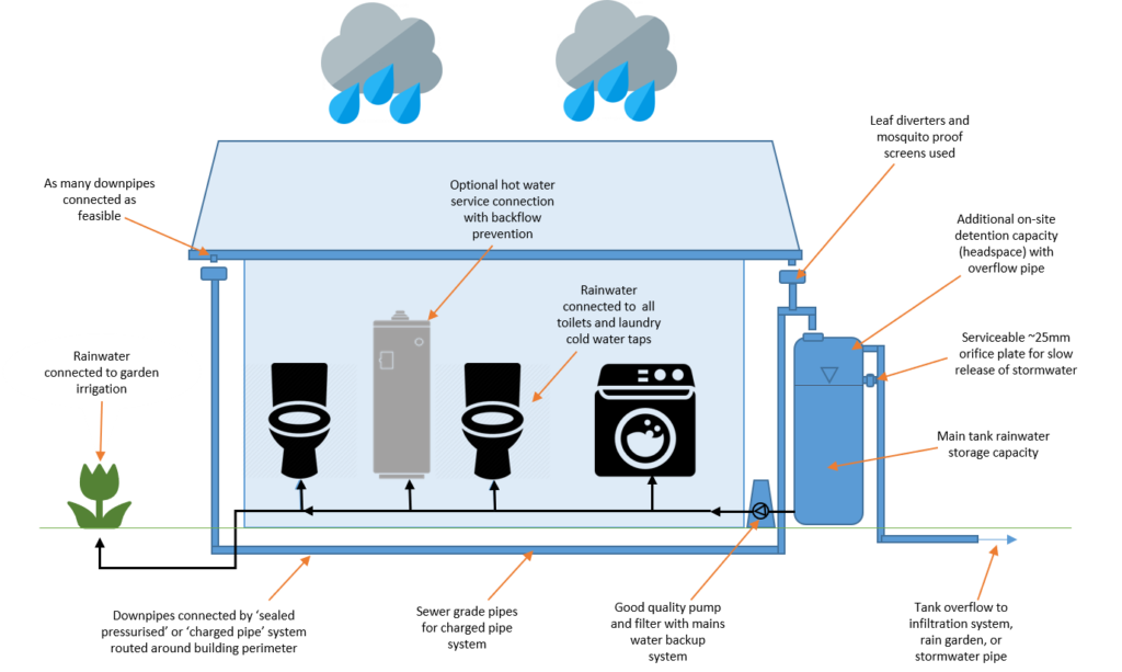
Figure 4 Simplified diagram of common rainwater tank installations
Design and application
To maximise rainwater re-use and reduce potable water supply, it is recommended that rainwater tanks be plumbed to all toilets, washing machines, laundry cold water outlets, and irrigation systems for any landscaped areas of the site. Rainwater tanks can also be connected to hot water services that include a water storage component, however these systems must comply with the National Construction Code (NCC) of Australia[1]. Considerations for connecting rainwater to hot water services are:
- ensure hot water is uniformly heated to 60° to “sterilise” it for contact use.
- install a fine mesh filter prior to hot water service inlet pipe to improve water quality – periodic maintenance is required
- ensure good quality pump is used to prevent fluctuation of water pressure and hence maintain a constant shower temperature
- install backflow prevention valve(s) as per NCC requirements.
Additional treatment is generally required when rainwater is to be used as a drinking water supply.
To ensure clean water supply in your rainwater re-use system, it is recommended that gutters are fitted with appropriate leaf guards, rainheads are fitted to downpipes, first flush diverters are fitted prior to the tank storage and mosquito screens fitted at the end of all pipes.
Rainwater tanks can include stormwater detention capabilities. These systems are referred to as combination retention/detention systems. The detention storage component is typically located at the top of the tank, with a restricted outlet orifice provided at a calculated height above the base of the tank to control peak flows. The detention component remains empty except during a rain event. The retention component is the permanent volume of stormwater stored at the bottom of the tank (below the restricted outlet orifice) that is available for use. Further information regarding detention systems is below.
Infiltration systems
Infiltration systems consist of a shallow excavated trench, soakage well or tank, designed to retain a certain volume of stormwater runoff. The stored water permeates into surrounding soils, significantly reducing runoff volumes, having provided a pathway for treated runoff to recharge local groundwater aquifers and, in turn, surface water resources.
There are several different types of infiltration systems that are available to the designer, each of which suit different sites and applications. These are:
- infiltration trenches
- infiltration basins
- soakage wells or pipes
- permeable pavement
- infiltration swales.
Infiltration systems function best when high-infiltration soil types are present (sand or mildly reactive clays). Many suburbs within the metropolitan Adelaide area are characterised by reactive clays not suited to these systems. An estimation of a sites soil type can usually be determined by looking at the site’s soil report that is used for foundation design. Alternatively, for more accurate results, a geotechnical engineer can be engaged to undertake site soil classification and percolation testing.
Design and application
Guidance for the use of infiltration trenches and infiltration wells is outlined in WSUD: Basic procedures for “source control” of stormwater – a handbook for Australian practice[2]. Also recommended is WSUD Engineering Procedures Stormwater eBook by Melbourne Water available on the Amazon.com.au Kindle Store
The use of on-site gravel trenches or soakage well infiltration systems in proximity to buildings and other structures is restricted to soil types classified as class A (Stable, non-reactive), Class S (Slightly reactive clay), class M (Moderately reactive clay) or class M-D (Deep moderately reactive clay).
To protect nearby footings, slabs and other structures from cracking due to movement, the surface movement due to soils should be equal to or less than 25 mm, as defined in AS 2870 and where the following conditions exist:
- The slope of the natural ground does not exceed 1 in 10;
- The depth to rock is 1.2 m or greater; and
- The groundwater table is permanently below 1.5 m from the natural ground surface or the final ground surface, whichever is the lowest.
Pre-treatment of water for removal of debris and sediment is essential. Pre-treatment measures include leaf filters for roof runoff, and sediment sumps, vegetated swales, bioretention systems or sand filters for surface runoff.
The use of on-site infiltration devices is not usually recommended on sites classified as reactive soils of type H / H-D, H1 / H1-D, H2 / H2-D, E / E-D and P as defined in AS 2870, unless under advice from a structural engineer. For a description of these soil types see the Glossary.
| Soil type | AS 2870 Classification | Soil Hydraulic Conductivity (Kh)[3] | Minimum clearance from structures and boundaries |
| Sandy soils and sandy loam | Class A | 5 × 10⁻⁵ m/s (180 mm/hr) or greater | 1 metre |
| Sandy clay | Class S | between 1 × 10⁻⁵ and 5 × 10⁻⁵ m/s (36–180 mm/hr) | 2 metres |
| Weathered or fractured rock | Class A | between 1 × 10⁻⁶ and 1 × 10⁻⁵ m/s (3.6–36 mm/hr) | 2 metres |
| Medium clay | Usually Class M / M-D | between 1 × 10⁻⁶ and 1 × 10⁻⁵ m/s (3.6–36 mm/hr) | 4 metres |
| Heavy clay | Usually Class M / M-D | between 1 × 10⁻⁸ and 1 × 10⁻⁶ m/s (0.036–3.6 mm/hr) | 5 metres |
Infiltration pit sizing
InSite water can provide an area for infiltration. This area can be interpreted as 1 m deep and therefore equate to cubic meters of infiltration required. for Sizing the device, you can use the formula: Size = Treatment Volume / Void Ratio Where: Size = size of the pit or trench in cubic meters Treatment Volume = volume required by the InSite water calculations Void Ratio = available storage in the medium you are using Typical Void Ratios are: Sand and Gravel = 0.3 (range 0.25 to 0.4), Pipe or circular hollow pit = 0.78, Hollow ‘egg crate’ type structure = 0.9, Unlined Raingarden Soils = 0.2. Details for sizing an infiltration pit can be found in:
- WSUD: Basic procedures for “source control” of stormwater – a handbook for Australian practice[4]
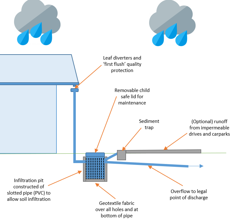
Figure 5 Example infiltration pit
Infiltration trench sizing
Details for sizing an infiltration pit can be found in:
- WSUD: Basic procedures for “source control” of stormwater – a handbook for Australian practice[6]
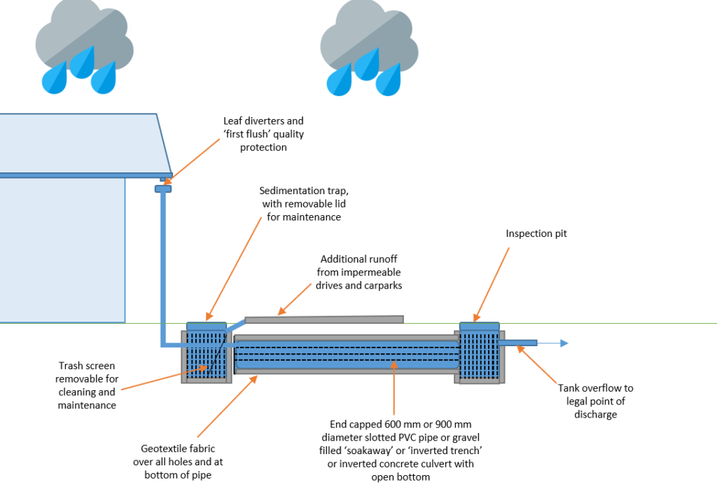
Figure 6 Example infiltration trench
Permeable pavement systems
Permeable pavement systems are pavement systems that allow stormwater to percolate through to a sub-surface course, from where it either infiltrates to the soil or is filtered back to the drainage system to subsurface soils or storages to reduce stormwater runoff. Underlying pavement layers can also include perforated pipes that allow the release of stormwater runoff into the receiving drainage system.
Permeable pavement systems provide two main advantages over regular impervious pavements: Improved water quality through filtering, interception and providing biological treatment; and reduced stormwater flow through infiltration and storage.
Permeable pavement systems commonly include interlocking block paving, porous concrete or plastic grids that provide structural stability to gravel or grassed paths, driveways and car parks. Single-sized gravel can also be used as an effective method of reducing stormwater runoff in low-traffic footpath and driveway areas.
Design and application
Pervious pavement systems fall into two distinct categories:
- Porous surfaces: Comprising a layer of highly porous material (e.g. specially designed concrete or asphalt).
- Permeable pavements: Comprising a layer of interlocking paving blocks (either made with porous material or specially shaped to allow the ingress of water by way of vertical slots) to allow runoff through to the underlying surface.
Interlocking pavements or other systems rated to handle traffic are recommended where high traffic loads can be expected
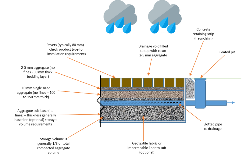
Figure 8 Example cross section of porous pavers
Bioretention systems (raingardens, bioswales and bioretention)
Bioretention systems are also known as raingardens, biofilters, bio-infiltration systems and bioremediation systems. Common types of bioretention systems are:
Raingardens improve stormwater water quality by slowly filtering water through the soil layer to the drainage pipe at the base. Stormwater flows are diverted and pollutants removed through the processes of settlement (sedimentation) binding with components in the filter media, and by the action of specially selected plants and the associated microbial community.
Bioretention basins are shallow planted depressions that assist in redistributing excess rain and stormwater runoff from the roof of a development, as well as pervious and impervious surfaces. The process assists the rainwater and stormwater runoff to infiltrate the underlying soil, recharge the groundwater and reduce peak flows from the development.
Bioretention swales and bioretention buffer strips serve an identical purpose as bioretention basins in that they reduce the volumetric flow of stormwater and improve stormwater quality. Bioretention swales usually include gravel storage volume. The void spaces in gravel helps store runoff from impervious areas (i.e. a carpark or driveway).
Design and application
For Australian conditions, a rule of thumb guide is for the area of your raingarden to be between 0.5‑2.0% of the area of the contributing catchment (e.g. area of roof or other impervious surfaces draining to the raingarden). For more information and tools for sizing and designing a raingarden talk to your local Council drainage officer or local Water Authority.
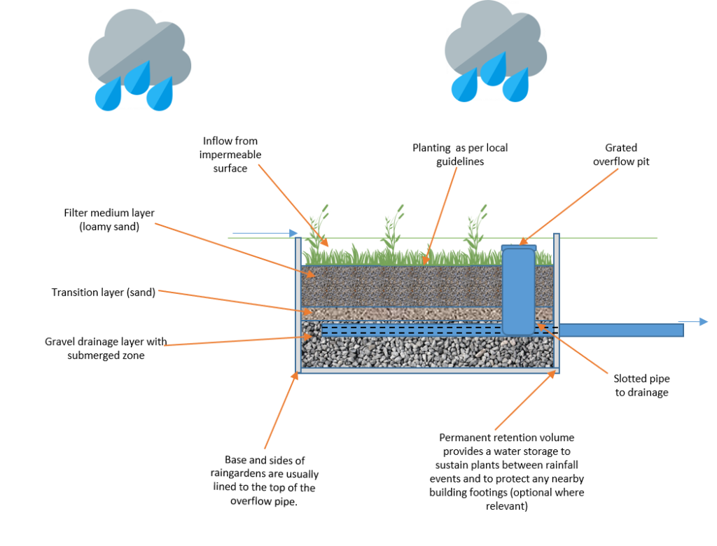
Figure 10 Bioretention raingarden.
Grass buffers and swales
Grass buffers are vegetated strips that convey hard runoff from an impermeable surface to a downstream drainage system. Buffers are effective in removing coarse and medium sized sediment from stormwater.
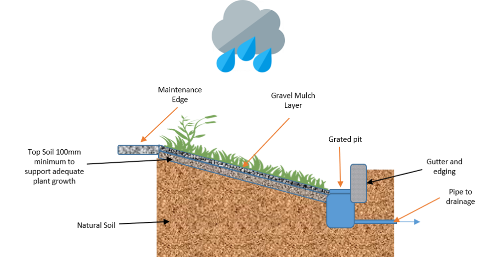
Figure 11 Grass Buffer simplified diagram
Grass swales are formed, vegetated channels that are used to convey runoff from impervious areas. They are typically shallow, linear, and wide. Grass swales can become features in the landscape, require minimal maintenance once established, and are hardy enough to withstand large flows. Grass swales differ from bioretention swales in that they normally have no underlying gravel and drainage layers.
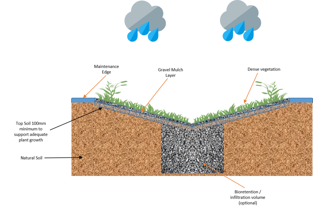
Figure 12 Swale simplified diagram
Design and application
Ensure levels are correct so that runoff can enter the buffer unimpeded. Buffer strips are typically grassy areas although a range of species could be used. More detailed technical advice on the design on these systems can be found in Water Sensitive Urban Design – Greater Adelaide Region Technical Manual, Chapter 11 (Swales and Buffer Strips) and the WSUD Engineering Procedures: Stormwater, which can be purchased at www.publish.csiro.au/book/4974
Green roofs and living walls
Green roofs and living walls can provide reduced energy costs, natural insulation, establish peaceful areas for individuals and a place for wildlife, as well as, absorb and treat stormwater. Additionally, green roofs improve air quality and aid in reducing the urban heat island effect; a condition in which cities and suburban developments absorb and trap heat.
Design and application
Green roofs and living walls consist of a series of substrate layers to support drainage on top of built structures, provide thermal insulation, and can ameliorate the urban heat island effect[9]. The layers incorporated within green roofs and living walls must accommodate drainage and protect the built structure from moisture and water ingress. This is achieved through the inclusion of a waterproof membrane in the design. High-quality root repellent systems are also required for green roofs and living walls to further protect the surrounding structures.
The most appropriate green roof for Australia is a deeper substrate, which consists of depths between 150 and 600 millimetres of growing medium. Care should be taken that a structural engineer certifies that the building design can support a green roof, and that the design is resistant to heatwaves, as green roofs can “cook” in high temperatures, killing the vegetation. Design responses to improve performance in high temperatures can include deeper growing medium; water storage crystals; effective irrigation; partial shading with vegetation or structures, e.g. solar panels; and the use of annual native grasses and other summer heat resistant species.
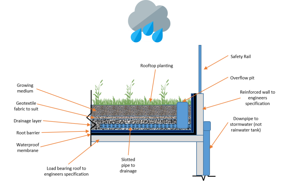
Figure 14 The various layers constituting a green roof design
On-site detention (OSD) tanks
Detention systems are similar to retention systems, however the captured stormwater runoff is only temporarily “detained” for a short period of time, with stormwater discharged at a controlled (reduced) outflow rate. This helps to limit impacts on the capacity of the receiving drainage system. Stormwater detention systems remain empty at all times, except during or immediately after a rain event occurs.
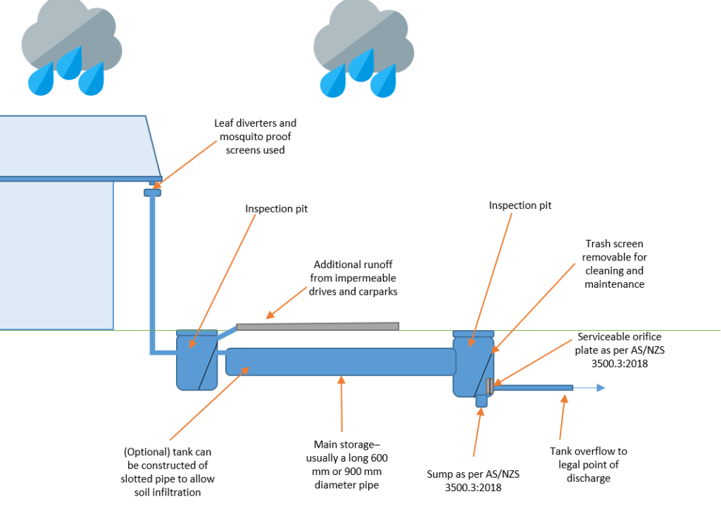
Figure 15 Typical underground stormwater detention tank
Design and application
Detention tanks are useful in areas where current stormwater infrastructure has aged – particularly where urban areas have densified over time, increasing impermeable areas connected to existing drainage systems. The installation of a detention tank aims to reduce local drainage overcapacity in existing infrastructure.
The effect is usually only locally beneficial, with overall catchment flood volumes remaining the same. The flow rate from the tank may be regulated by the size of the tank and orifice outlet. Onsite detention tanks must be designed to suit the requirements of the proposed building development and its location in the catchment. For more information see local Council and stormwater authority guidelines and AS/NZS 3500.3 (Stormwater Drainage).
Water efficient fixtures and appliances
Developments must incorporate water efficient appliances and fixtures such as showerheads, dishwashers, washing machines, basins, kitchen taps and toilets. The Australian Water Efficiency Labelling and Standards (WELS) scheme is an Australian Federal system established to rate appliances based on their water efficiency. It works by assigning a relevant WELS rating (WELS Star rating) label to certain products.
Design and application
Projects should aim to meet best practice water efficiency standards wherever possible. The below recommended WELS ratings performance criteria has been specified in comparison with the industry benchmark.
Table 1 Water efficient appliances and fixtures – WELS Rating and associated water savings against industry benchmark, performance criteria and best practice
| Typical fixture | Minimum requirements (used in InSite tool) | Best practice |
| Basins | 4 Star WELS | 5 Star WELS |
| Kitchen taps | 4 Star WELS | 5 Star WELS |
| Toilets | 4 Star WELS | 5 Star WELS |
| Showerheads | 3 Star WELS (with flow between 7.5–9 litres/minute) | 3 Star WELS (with flow between 6–7.5 litres/minute) |
| Urinals | 4 Star WELS | 5 Star WELS |
| Dishwashers | 3 Star WELS | 5 Star WELS |
| Washing machines | 3 Star WELS | 5 Star WELS |
| Baths | Medium Sized Contemporary Bath | Small square tub/combined shower |
The 25% potable (mains) water reduction performance target compared to a building that has no water saving features can generally be met by using a combination of efficient water fittings and a rainwater tank to supply water for appropriate household uses. This section provides recommended fitting specifications in accordance with the Australian Water Efficiency Labelling and Standards (WELS) for water efficiency of fittings[10].
Glossary of terms
| Term | Definition |
| AEP | Annual exceedance probability is defined as: The probability that a given rainfall total accumulated over a given duration will be exceeded in any one year. With ARI expressed in years, the relationship is: AEP = 1 – exp (-1/ARI). Further discussion of stormwater terminology can be found in Book 1; Chapter 2; Section 2.2 Terminology of ARR 2016 http://arr.ga.gov.au/arr-guideline |
| ARI | Average recurrence interval is defined as: The average, or expected, value of the periods between exceedances of a given rainfall total accumulated over a given duration. |
| ARR 2016 | Australian Rainfall and Runoff (Engineers Australia 2016, published at http://arr.ga.gov.au) is a national guideline document, data and software suite that is the default national standard for the estimation of design flood characteristics in Australia. |
| Deemed to satisfy | A simplified checklist approach to achieving compliance targets (as opposed to a custom designed or software modelled approach). |
| ESD | Environmentally sustainable development |
| EY | Exceedances per year The number of times an event is likely to occur or be exceeded within any given year. |
| Infill growth | Growth occurring through densification of existing developed areas. |
| InSite Water | An integrated water cycle management design toolkit focused on Council approvals for infill growth www.insitewater.com.au |
| IFD | Intensity-frequency-duration Data generated for engineers and hydrologists to understand design rainfall events http://www.bom.gov.au/water/designRainfalls/ifd/ The 2016 Intensity–Frequency–Duration (IFD) design rainfalls are provided for use in conjunction with the 2016 edition of Australian Rainfall and Runoff (ARR 2016) |
| Integrated water management | A multi-disciplinary and multi-objective approach for the sustainable use of available resources with the objectives of environmental protection, and minimising water demands, wastewater discharges and stormwater runoff. |
| Kh | Saturated Hydraulic Conductivity. If no data is available for a site, field hydraulic conductivity tests must be undertaken to confirm assumptions of soil hydraulic conductivity adopted during the concept design stage. Field soil hydraulic conductivity (Kh) can be determined using the falling head auger hole test method. |
| OSD | On site detention A common practice of slowing down stormwater release rates into stormwater drains by using a detention tank with a known outflow rate. |
| Rainwater | Rainfall collected from the roofs of buildings. |
| Rainwater tank | A water tank that is used to collect and store rainwater runoff, typically from rooftops via rain gutters. |
| Soil site classification | Soils site classification is according to Australian Standard AS 2870/2011 – Residential slabs and footings Site classifications and movement are based on soil reactivity Class A (0-10mm) Stable, non-reactive. Most sand and rock sites. Little or no ground movement likely as a result of moisture changes. Class S (10-20mm) Slightly reactive clay sites. May experience slight ground movement as a result of moisture changes. Class M / M-D (20-40mm) Moderately reactive clay or silt sites. May experience moderate ground movement as a result of soil conditions and moisture changes. Class H1 / H1-D (40-60mm) Highly reactive clay sites. May experience a high amount of ground movement as a result of soil conditions and moisture changes. Class H2 / H2-D (60-75mm) Highly reactive clay sites. May experience very high ground movement as a result of soil conditions and moisture changes. Class E / E-D (75mm+) Extremely reactive sites. May experience extreme amounts of ground movement as a result of soil conditions and moisture changes. Class P (this is approximately 70% of building sites in Australia) Problem sites. Sites may be classified as ‘Class P’ as a result of mine subsidence, landslip, collapse activity or coastal erosion (e.g. dunes), soft soils with a lack of suitable bearing, cut and/or filled sites, or creep areas. Ground movement as a result of moisture changes may be very severe. If you are building on a Class P site you will need to consult a structural engineer. The ‘D‘ inclusion (i.e M-D, H1-D, H2-D or E-D) The ‘D’ in these classifications refers to ‘deep’ movements in soil due to deep variances in moisture. These classifications are mostly found in dry areas. |
| Stormwater | Rainfall that runs off all urban surfaces such as roofs, pavements, car parks, roads, gardens and vegetated open space. |
| tc | tc – “time of concentration” reserved for SITE-ONLY (runoff) travel time |
| Tc | Tc – “critical storm duration”, a CATCHMENT-WIDE PROPERTY |
| TN | Total nitrogen The sum of the nitrogen present in all nitrogen-containing components in a given water sample at certain temperature over a specific time period. Best practice is a 45% reduction target of typical urban annual load. |
| TP | Total phosphorus The sum of the phosphorus present in all phosphorus-containing components in a given water sample at certain temperature over a specific time period. Best practice is a 45% reduction target of typical urban annual load. |
| TSS | Total suspended solids A water quality measurement of the mass of fine inorganic particles suspended in a given water sample at a certain temperature over a specific time period. Best practice is an 80% reduction target of typical urban annual load. |
| WELS | Australian Water Efficiency Labelling Standards scheme. |
| WSUD | Water sensitive urban design Design principles that aim to reduce the impact of interactions between the urban built form and the urban water cycle including surface water, potable water, groundwater, urban and roof runoff, wastewater and stormwater. |
References
[1] See NCC Plumbing Code of Australia PCA (Volume Three), Australian Building Codes Board, latest version at https://www.abcb.gov.au/
[2] Argue JR (2004/2013) WSUD: Basic procedures for “source control” of stormwater – a handbook for Australian practice. Urban Water Resources Centre, University of South Australia.
[3] Water, Melbourne. WSUD Engineering Procedures: Stormwater: Stormwater (Kindle Locations 6606-6609). CSIRO PUBLISHING. Kindle Edition. Available on the Amazon.com.au Kindle Store
[4] Argue JR (2004/2013) WSUD: Basic procedures for “source control” of stormwater – a handbook for Australian practice. Urban Water Resources Centre, University of South Australia.
[5] Minister’s Specification SA 78AA September 2003 On-Site Retention of Stormwater is available online at https://www.sa.gov.au/__data/assets/pdf_file/0017/7046/SA_78AA_Onsite_retention_of_stormwater.pdf
[6] Argue JR (2004/2013) WSUD: Basic procedures for “source control” of stormwater – a handbook for Australian practice. Urban Water Resources Centre, University of South Australia.
[7] Minister’s Specification SA 78AA September 2003 On-Site Retention of Stormwater is available online at https://www.sa.gov.au/__data/assets/pdf_file/0017/7046/SA_78AA_Onsite_retention_of_stormwater.pdf
[8] See Water Sensitive SA Guide to raingarden plant selection and placement http://www.watersensitivesa.com/resources/publications-2/guidelines/bioretention/
[9] For more information see the Growing Green Guide: A guide to green roofs, walls and facades in Melbourne and Victoria http://www.growinggreenguide.org/
[10] See http://www.waterrating.gov.au/ for more information on WELS ratings
Disclaimer
This guide is of a general nature only. Advice from a suitably qualified professional should be sought for your particular circumstances. Depending on each unique situation, there may be occasions where compliance is not achieved. The following is outside the scope of this guide, however it is critical that all designers consider the following:
- Manage expectations and risks around occasional surface water and ponding.
- Ensure that uncontrolled stormwater does not flow over property boundaries or otherwise cause a nuisance.
- Plan for major flood pathways – locate away from, adapt (raise floors above predicted flood levels) and defend buildings against potential major flooding.
- Plan to reduce annual average damages and safety risks.
- Take into account local conditions such as slope, topography and soils (type, reactivity, permeability, water table level, salinity, dispersiveness, acid sulphate soils, etc.).
- Ensure that soil moisture and building clearance is considered in areas of reactive clays or where varying soil moisture levels could damage buildings, infrastructure or other constructions.
- For steeper sites, ensure the design includes geotechnical considerations such as slope stability with varying soil saturation levels.
- Compliance with other Australian Standards, laws, guidelines, regulations and Council requirements.